
28 min read ·
How Fusion-Bonded Epoxy Protects Steel—and What Determines Whether It Works
FBE can require high substrate heat during application while having a substantially different allowable operating temperature after cure.
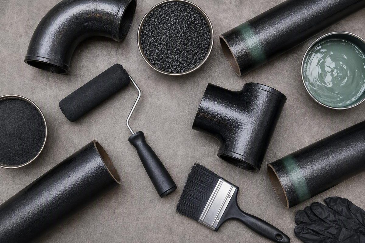
Fusion-bonded epoxy, or FBE coating, is used to protect steel pipe and related components from corrosion. The name alone, however, does not establish whether a finished coating is suitable for a particular pipeline, water system, internal lining, valve, fitting, repair, or field joint.
FBE is not ordinary epoxy paint. It is a heat-activated thermosetting powder system. Its performance depends on the steel surface, powder formulation, application temperature, film formation, cure, inspection, handling, repairs, and compatibility with the completed installation. A suitable powder can fail when applied incorrectly, while a well-applied coating can still be unsuitable for the intended temperature, chemical exposure, immersion conditions, or regulatory requirements.
This guide is therefore an orientation to the technology and the questions a project should resolve—not a substitute for a coating specification or inspection procedure. Current governing documents, product-specific technical data, qualification evidence, and a procedure reviewed by qualified coating or corrosion personnel must control the work.
What fusion-bonded epoxy coating is
FBE stands for fusion-bonded epoxy. It is an epoxy-based thermosetting powder applied to properly prepared steel that has been heated into the powder’s specified application window.
The basic bonding sequence is:
- The steel is cleaned and abrasive-blasted.
- Blasting creates the required surface cleanliness and profile.
- The prepared steel is heated.
- Electrically charged powder is sprayed toward the grounded steel.
- The powder melts when it contacts the hot surface.
- The liquid epoxy flows across and wets the blast profile.
- The coating gels and chemically cross-links.
- Continued time and heat develop the required cure.
- The film cools into a continuous solid coating.
Chemical cross-linking makes FBE a thermoset. Once properly cured, it does not soften and remelt like a thermoplastic. That does not mean the coating can withstand unlimited heat or every chemical environment. Each formulation has its own processing and service limits. One applicator describes typical application temperatures of 180–250°C, but that range concerns processing rather than a universal operating limit for the cured coating (Bayou Companies’ FBE process description).
FBE versus ordinary liquid epoxy
A conventional liquid epoxy is commonly supplied as a resin and curing agent that are mixed before use. Depending on the product, it may be applied by spray, brush, roller, or other suitable equipment and may cure at or near ambient temperature. Mixing ratio, pot life, environmental conditions, recoat intervals, and full cure still require control.
FBE arrives as a formulated dry powder. Application requires heated steel, powder-handling equipment, electrostatic deposition, controlled fusion, and a verified cure cycle. These requirements generally favor a controlled coating line for production work.
Liquid epoxy can be more practical for repairs, field work, existing structures, irregular components, or locations where heating the complete item into an FBE application window is impractical. That practical distinction does not make either technology universally superior. Meaningful comparisons require matched surface preparation, thickness, cure, exposure, test conditions, and acceptance criteria.
What the FBE designation does not specify
FBE identifies the coating technology. It does not define:
- Pipe grade
- Seamless or welded manufacturing route
- Diameter or wall thickness
- Pressure rating
- Mechanical properties
- Dimensional tolerances
- End preparation
- Internal cleanliness
- Suitability for the transported product
- Potable-water or food-contact approval
- Maximum operating temperature
- Expected service life
A purchase order for “FBE-coated pipe” is therefore incomplete unless it separately defines the base steel product, coating configuration, service environment, qualification basis, inspection requirements, field-joint system, and repair rules.
Generic online values should not be promoted into project requirements simply because they are described as typical. The selected powder’s technical data, governing project documents, applicable current standards, qualified application procedure, and agreed inspection plan take precedence.
Where FBE is used and which configuration fits the job
FBE systems are used on external steel pipelines, connections, fittings, valves, hydrants, and components in water and sewage infrastructure. They may also be selected for particular internal surfaces and industrial services. These applications do not imply that one powder is interchangeable across them.
The useful selection question is not simply, “Should this project use FBE?” It is, “Which FBE-based configuration has evidence supporting this exposure and installation method?”
Single-layer external FBE
Single-layer FBE is applied directly to prepared steel as the primary corrosion-control barrier. It is commonly considered for buried or submerged pipe and may be used with a separately designed cathodic-protection system.
Its barrier function depends on continuity. Holidays, handling damage, defective repairs, poorly coated cutbacks, and incompatible field joints create paths through which the environment can reach the steel. Evaluation must therefore cover the installed system rather than only the factory-coated pipe body.
Selection should consider the qualified service temperature, soil or water exposure, storage period, installation stresses, handling controls, and project acceptance requirements. Previous use of an unspecified “FBE coating” on another project is not evidence that a proposed powder is suitable.
Dual-layer abrasion-resistant FBE
Dual-layer FBE generally combines:
- A base FBE layer that provides adhesion and primary corrosion protection; and
- An abrasion-resistant overlay intended to improve resistance to impact, gouging, or construction damage.
Its suitability still depends on the complete qualified system.
The project should determine whether the overlay is compatible with the base layer, bending procedure, field-joint materials, repair products, inspection methods, and expected installation loads. “Dual layer” is a configuration description, not a guarantee against all mechanical damage.
FBE in 3LPE and 3LPP systems
FBE can also serve as the epoxy primer in a three-layer polyethylene or three-layer polypropylene coating. In broad terms, these systems contain:
- FBE bonded to the prepared steel;
- An adhesive or tie layer; and
- An outer polyethylene or polypropylene layer.
The FBE provides the steel-bonded corrosion-control foundation. The outer layers change the system’s mechanical and environmental protection. They also change requirements for cutbacks, field joints, damage detection, transitions, and repairs.
It is therefore misleading to frame 3LPE or 3LPP as wholly unrelated alternatives to FBE. They are multilayer systems that incorporate an FBE primer while creating a different overall coating structure.
Internal FBE lining
Internal FBE must be specified separately from external FBE. The internal coating is exposed to the transported medium rather than soil or groundwater. Relevant variables may include fluid chemistry, solids, flow conditions, cleaning methods, pressure cycling, immersion, temperature, and regulatory contact requirements.
A powder qualified for external pipeline service is not automatically suitable for:
- Internal flow service
- Potable water
- Food contact
- Hydrocarbon immersion
- Process chemicals
- Sewage exposure
- Elevated-temperature fluids
- Flow-enhancement duties
Supplier coverage confirms that FBE can be applied to both internal and external pipe surfaces and that temperature-specific formulations may be needed (Kelly Pipe’s discussion of internal, external, and temperature-specific FBE). Actual suitability must be demonstrated for the proposed product and service.
FBE for field joints
FBE is strongly associated with factory coating lines, but it is not inherently factory-only. Specialized field-joint equipment can align the weld area and move electrostatic spray guns around the pipe to apply FBE as a single layer or base primer (RAE Energy’s field-joint FBE equipment overview).
A successful plant process does not automatically qualify the field-joint process. The joint system requires its own documented compatibility and application controls.
How to decide whether FBE suits a service environment
Coating selection should begin with the complete exposure and installation profile. At minimum, document:
- Coating location: external pipe body, internal lining, fitting, valve, field joint, repair, or another component
- Transported medium: including expected contaminants, treatment chemicals, solids, and composition changes
- Temperature: minimum, continuous operating maximum, normal excursions, and credible peaks
- External exposure: soil, groundwater, fresh water, seawater, atmosphere, or intermittent immersion
- Installation method: open trench, offshore installation, bore, pull-through, directional drilling, or aboveground service
- Mechanical exposure: lifting, stacking, transport, bending, abrasion, impact, gouging, backfill, or pull forces
- Electrical environment: cathodic protection, AC interference, and DC stray-current exposure
- Storage: duration, sunlight, moisture, contamination, and support conditions
- Regulatory requirements: particularly for potable water, food contact, or other controlled internal uses
- Acceptance criteria: tests, sampling, hold points, repairs, retesting, and documentation
Internal and external exposures must be assessed independently. External coating may face wet soil, salts, rock contact, installation damage, and interaction with cathodic protection. Internal lining may face continuous chemical immersion, entrained solids, cleaning agents, or elevated-temperature fluid. Qualification for one side of the pipe does not transfer automatically to the other.
Temperature: processing is not service
Published FBE guidance commonly identifies 180–250°C as a typical substrate-temperature range during application (Bayou Companies’ process guidance). That range describes the heated steel used to melt, flow, and cure the powder. It is not a universal continuous service-temperature range for the finished coating.
The distinction is essential. A coating can require high substrate temperature during application while having a substantially different allowable operating temperature after cure. Conversely, special powders may be formulated for unusual processing or service conditions.
Product data and qualification evidence should address two separate questions:
- What steel-temperature and time window is required during application and cure?
- What temperatures may the cured coating experience in service?
Low-temperature flexibility, elevated-temperature exposure, chemical immersion, potable-water contact, and prolonged wet service all require formulation-specific evidence.
Mechanical and ultraviolet exposure
An exposed single-layer coating may be damaged during loading, transport, stacking, bending, trenching, backfilling, or pull-through installation. Possible responses include stricter handling controls, protective padding, selected backfill, rock shielding, an abrasion-resistant overlay, or a qualified multilayer system. The appropriate choice depends on the defined damage exposure.
Prolonged ultraviolet exposure before installation may also be relevant for a coating intended principally for burial. A vendor overview identifies mechanical impact and extended ultraviolet exposure as limitations to consider for single-layer FBE, but project controls should come from the selected system’s documentation rather than a generic storage rule (Allland’s overview of FBE configurations and limitations).
Compact coating-selection matrix
| System | Typical application setting | Principal selection issue |
|---|---|---|
| Single-layer external FBE | Buried or submerged steel pipe with controlled handling and compatible cathodic protection | Whether the qualified film suits the temperature, external environment, storage, and installation damage |
| Dual-layer abrasion-resistant FBE | Directional drilling, rough handling, rocky terrain, or increased gouge and abrasion exposure | Compatibility and qualification of the base layer, overlay, bending, field joints, detection, and repairs |
| FBE-based 3LPE or 3LPP | Pipe requiring an FBE primer plus additional outer mechanical or environmental protection | Polymer selection, temperature, layer interfaces, field joints, damage detection, and repair planning |
| Internal FBE lining | Water, sewage, hydrocarbon, industrial, or other specifically qualified internal service | Chemical, immersion, temperature, hygiene, regulatory, cleaning, and flow-condition qualification |
| Liquid epoxy | Field coating, repairs, irregular geometry, or work where high-temperature powder application is impractical | Surface preparation, mixing, ambient cure conditions, thickness, recoat limits, and compatibility |
Stop the selection process if the medium, temperature range, regulatory approval, installation stresses, or acceptance criteria remain undefined. Without those inputs, the project is not ready to choose a coating system.
The FBE application process, step by step
FBE application is a linked process. Each stage establishes conditions required by the next, and final inspection cannot reliably reconstruct every preparation, temperature, or cure problem that occurred earlier.
The following sequence is descriptive rather than a universal application procedure. Actual methods, limits, sampling frequencies, and dispositions must come from the approved product and project documents.
1. Incoming inspection and preliminary cleaning
Before blasting, the applicator checks component identity and condition. Oil, grease, dirt, marking compounds, temporary preservatives, sharp projections, weld irregularities, or other fabrication features may interfere with coating.
Hydrocarbons, ionic salts, rust, scale, dust, and other residues can inhibit wetting or adhesion. Cleaning methods must remove the relevant contamination without leaving another harmful residue.
2. Abrasive blasting
Blasting performs two related functions:
- It removes rust, mill scale, and other surface material to reach the required visual cleanliness.
- It creates an anchor profile that the melted epoxy can wet and follow.
SSPC-SP 10/NACE No. 2 near-white-metal blast cleaning is frequently referenced in FBE guidance, but it should not be treated as an automatic requirement for every component. AMPP associates inadequate cleanliness, residual contaminants, and an unsuitable profile with poor adhesion and recommends checking soluble salts and limiting delay between blasting and coating (AMPP’s FBE application and inspection guidance).
Published profile ranges vary because powder formulations, steel condition, abrasive type, thickness, geometry, and qualification procedures differ. A profile copied from an unrelated web page may be too shallow for one coating or too severe for another.
The approved procedure should define the required profile, measurement method, instrument checks, sampling locations, frequency, and acceptance limits.
3. Cleanliness and profile verification
Before heating, inspection commonly considers:
- Visual cleanliness
- Surface profile
- Dust and residual abrasive
- Soluble salts where required
- Oil or grease
- Moisture
- Flash rust
- Recontamination
- Time since blasting
A clean blasted surface can deteriorate through delay, moisture, dirty air, contaminated handling equipment, or unsuitable storage. If the specified condition is lost, the governing procedure should determine whether recleaning, reblasting, or another disposition is permitted.
4. Preheating
Prepared steel is heated by a controlled method such as induction or an oven. Temperature must be measured at defined locations with suitable, verified instruments.
Insufficient heat may prevent proper fusion, flow, wetting, or cure. Excessive heat may contribute to discoloration, sagging, or degradation. AMPP identifies 180–250°C as a typical preheat range, while directing applicators to the powder manufacturer’s technical data for the actual parameters (AMPP’s temperature-control guidance).
The relevant value is the steel temperature entering the application zone—not simply the heater setting or a reading taken at an unrepresentative location.
5. Electrostatic powder application
Spray equipment charges the FBE powder, while the steel is electrically grounded. The charged particles are attracted to the component and deposited on its surface.
On contact with hot steel, the powder melts and begins to flow. Process variables may include powder identity and condition, feed rate, gun position, voltage, grounding, spray pattern, line speed, environmental conditions, and coverage of complex geometry.
6. Fusion, gel, and cure
FBE does not simply “dry.” Several stages occur:
- Fusion: The powder melts into a liquid film.
- Flow and wetting: The liquid spreads across and follows the prepared surface.
- Gel: The material transitions from a flowing liquid toward a cross-linked network.
- Cure: Chemical reaction continues until the required coating properties develop.
Time and temperature work together.
7. Controlled cooling and optional quenching
After the required cure development, the coated item is cooled. Some qualified processes include water quenching at a defined stage. Cooling or quenching does not replace cure and should not be improvised from generic instructions.
The approved procedure should state when cooling begins, whether quenching is allowed, and when the film may be inspected, supported, moved, or packed.
8. Inspection, repair, and reinspection
The finished coating is visually examined and checked for specified thickness and continuity. Defects are assessed against the project’s repair limits.
Any repair material must be approved for the coating and service. Surface preparation, overlap, cure, thickness, continuity testing, and documentation should follow the accepted repair procedure.
Repairs must be reinspected after cure. The same principle applies to field joints, cutbacks, weld areas, and transitions.
9. Final identification and protection
Accepted components need identification that remains linked to their coating and inspection records. Marking, supports, separators, lifting equipment, restraints, cutback protection, and packing should be selected to avoid contaminating or damaging the coating.
Release should confirm both physical acceptance and traceability. A coating record that cannot be linked to the relevant pipe or component has limited value.
Inspection and process control: proving the coating was applied correctly
Inspection should examine both the finished film and the process that created it. A final thickness or continuity test cannot reveal every contaminant, temperature excursion, or cure problem.
The inspection and test plan should define responsibilities, hold points, instruments, sampling, acceptance criteria, records, and decision authority. The table below identifies questions commonly addressed; it does not prescribe universal limits or dispositions.
| Stage | Variable | Likely concern if uncontrolled | Inspection method | Procedure-controlled response | Required record |
|---|---|---|---|---|---|
| Incoming condition | Identity, surface defects, oil, grease, sharp projections | Contamination, thin areas, local damage, loss of traceability | Identity check and documented visual examination | Clean, dress, repair, segregate, or reject only as permitted | Item ID, heat number, condition, disposition |
| Preliminary cleaning | Hydrocarbons, salts, dirt, preservatives | Poor wetting, fisheyes, adhesion loss, blistering | Visual inspection and specified contamination tests | Repeat approved cleaning and verify | Method, item or lot, results |
| Abrasive blasting | Visual cleanliness | Residual rust, scale, or contamination | Comparison with the governing visual standard | Reprocess in accordance with the procedure | Standard used, inspector, time, result |
| Abrasive blasting | Anchor profile | Inadequate keying, peak penetration, locally thin film | Specified profile-measurement method | Adjust the process; reblast only where permitted | Instrument, locations, readings |
| After blasting | Soluble salts | Adhesion loss, blistering, underfilm corrosion | Specified extraction and test method | Apply the approved remediation and retest | Method, limit, result, retest |
| After blasting | Dust, moisture, flash rust, recontamination | Inclusions, pinholes, weak adhesion | Visual and specified cleanliness checks | Reclean or reblast as the procedure requires | Inspection time and disposition |
| Blast-to-coat interval | Delay and exposure | Recontamination or deterioration before coating | Time tracking and preheat-entry inspection | Reinspect and reprocess if required | Blast time, coating time, observations |
| Preheating | Steel temperature and uniformity | Incomplete fusion, under-cure, sagging, degradation | Qualified temperature-monitoring method | Correct equipment or line settings and segregate affected work | Instrument ID, readings, locations, settings |
| Powder handling | Product, batch, storage, condition, permitted reclaim | Contamination, poor flow, inconsistent cure | Batch and storage checks | Quarantine unsuitable material and investigate | Product, batch, shelf-life status, storage history |
| Spraying | Grounding, gun position, powder feed, line speed | Thin areas, holidays, pinholes, excessive buildup | Equipment checks and process monitoring | Stop or adjust the process; identify affected production | Settings, checks, operator, time |
| Film formation | Coverage and buildup | Missed areas, runs, sags, roughness | Visual checks and in-process thickness sampling | Adjust application; repair or reject as permitted | Readings and adjustments |
| Cure | Time-temperature history and approved cure indicator | Soft film, poor adhesion, reduced resistance | Process records and approved post-cure validation | Quarantine and assess under the approved procedure | Cure data, method, result, disposition |
| Final film | Dry-film thickness | Insufficient barrier or excessive buildup | Suitable verified gauge | Repair, recoat, strip, or reject only where authorized | Readings, locations, acceptance |
| Final film | Continuity | Pinholes, holidays, missed areas, repair defects | Detector selected for the system and thickness | Mark, repair, cure, and retest | Detector, setting, coverage, closure |
| Repairs and joints | Preparation, overlap, cure, thickness, continuity | Repair-edge or transition failure | Required visual, thickness, and continuity checks | Rework and repeat the acceptance sequence | Material, batch, applicator, tests |
| Release | Marking, cutbacks, packing, record linkage | Damage or lost traceability | Final documentation and shipment inspection | Correct before release | Release record and packing-list linkage |
Dry-film-thickness measurement
The gauge must be suitable for a nonconductive coating on steel and checked as required by the governing procedure.
There is no universal FBE thickness. The acceptable range depends on the product, coating configuration, component, service, qualification basis, and project. A typical value for one single-layer pipeline powder cannot automatically be applied to a dual-layer system, internal lining, fitting, valve, or field joint.
The measurement plan should define reading distribution, treatment of welds and edges, allowable local results, rounding rules, and the disposition of high or low readings.
Holiday detection
Holiday testing evaluates coating continuity by looking for an electrical path through the nonconductive coating to the steel. It can identify pinholes, bare areas, missed locations, and some repair defects.
The detector type and test voltage must be selected for the coating system, thickness, geometry, and governing procedure. Grounding, electrode contact, travel speed, equipment function, and complete coverage also matter. A voltage from an unrelated project should not be reused without confirming that it is appropriate.
Indications should be marked, repaired under the approved method, allowed to cure, and retested. Field joints, repairs, cutbacks, weld areas, fittings, and complex geometry require particular attention.
Visual inspection and cure verification
Visual examination should look beyond obvious bare steel. Relevant observations may include:
- Thin or translucent areas
- Excessive buildup
- Pinholes
- Fisheyes
- Sags or flow defects
- Rough or contaminated film
- Discoloration
- Inclusions
- Mechanical damage
- Poor transitions at repairs and cutbacks
Cure verification should use a method recognized for the selected product and process. MEK rub testing may be appropriate where the manufacturer or governing procedure allows it, but it is not a universal acceptance test.
Traceability and the limits of production acceptance
Records should connect each pipe or component to relevant production and inspection information, including:
- Item identity and heat number
- Powder manufacturer, product, and batch
- Cleaning and blasting results
- Profile and contamination checks
- Process temperatures and settings
- Cure-verification results
- Thickness readings
- Holiday-test results
- Repairs and retests
- Cutback measurements
- Final acceptance
- Packing and shipment records
These are production acceptance checks. Qualification tests address different questions, such as adhesion retention, impact, flexibility, abrasion, chemical resistance, cathodic disbondment, or behavior after thermal and immersion exposure.
Qualification establishes whether a system is a credible candidate for the service. Production control evaluates whether that system was applied within its approved process.
Common FBE defects, failure mechanisms, and field damage
Failure analysis should begin with evidence rather than a preferred explanation. Similar-looking defects may have different causes, and several mechanisms may operate at one location.
Adhesion loss
Possible contributors to adhesion loss include:
- Incomplete removal of rust or mill scale
- Residual oil or grease
- Soluble salts
- Dust or spent abrasive
- An unsuitable surface profile
- Flash rust
- Recontamination
- Steel temperature outside the qualified window
- Inadequate powder wetting
- Incomplete cure
- Incompatible repair or overcoating material
- Service outside the formulation’s qualification
Examination of the steel-coating interface may help distinguish loss of adhesion from failure within the coating itself.
Thin spots, pinholes, holidays, and excessive buildup
These conditions may be associated with powder delivery, gun settings, grounding, line speed, geometry, contamination, equipment condition, or inconsistent application.
Fisheyes can indicate localized wetting interference. Excessive buildup may occur where equipment position or electrostatic deposition concentrates powder.
Repairing visible defects without investigating the process can allow the same problem to continue through later production.
Under-cure and excessive heat
Under-cured FBE may remain soft or tacky and may not develop the intended adhesion or resistance. Possible contributors include low or nonuniform steel temperature, excessive line speed, inadequate retained heat, incorrect powder, or a cure schedule outside the approved window.
Excessive heat may be associated with discoloration, sagging, distortion, or degradation.
Mechanical damage during installation
A coating accepted at the plant can later be damaged by:
- Hooks, chains, forks, or unsuitable slings
- Point loading during stacking
- Transport vibration or restraints
- Bending
- Welding and joint preparation
- Trenching and lowering-in
- Rocky or contaminated backfill
- Directional-drilling pull-through
- Rollers, supports, or installation equipment
Handling and installation plans should identify inspection stages and responsibility for repairs. Inspection before lowering-in or pull-through can reveal damage that was not present when the coating left the plant.
Blistering and disbondment
A blister is an observation, not a complete diagnosis. Investigation may consider distribution, size, depth, adhesion at the edge, steel condition, exposure history, cathodic-protection records, and possible electrical interference.
Analysis of blister fluid—including pH, cations, chlorides, and other constituents—may help evaluate surface contamination or disbondment mechanisms. An AMPP conference-paper abstract identifies blister-fluid chemistry, soil corrosivity, and AC or DC interference monitoring as possible investigative tools, although the available abstract does not provide complete case data or universal diagnostic criteria (AMPP paper on FBE disbondment mechanisms).
FBE is often described as non-shielding to cathodic-protection current under normal conditions, including some disbonded or blistered conditions. That should not be interpreted to mean that disbondment is harmless. AC interference, DC stray current, inadequate cathodic protection, coating defects, aggressive soil, and localized corrosion still require engineering assessment.
Depending on the project and evidence, an investigation may consider direct examination, coating assessment, soil testing, cathodic-protection surveys, interference monitoring, coupons or probes, repair, rehabilitation, and review of plant and field records. The appropriate response must be determined by qualified personnel using the governing integrity-management requirements.
The meaningful unit of performance is the completed installation: plant coating, field joints, cutbacks, repairs, storage, handling, installation, and cathodic protection.
FBE versus liquid epoxy, 3LPE, 3LPP, and other alternatives
There is no universal winner. Proposed systems should be compared using the same substrate, environment, temperature, installation method, test conditions, and acceptance criteria.
FBE versus liquid epoxy
FBE generally suits controlled powder application to heated steel. It can form a thermoset film quickly, but it requires preparation, heating, grounding, powder delivery, cure control, and specialized inspection.
Liquid epoxy may be more practical for:
- Field repairs
- Small quantities
- Existing structures
- Irregular geometry
- Areas that cannot pass through a coating line
- Work where heating the complete item is impractical
Liquid systems have different controls, including mixing ratio, induction time where applicable, pot life, ambient temperature, humidity, dew point, film build, recoat window, solvent release where relevant, and full cure before service.
Convenient field application does not prove that a liquid epoxy matches the parent FBE’s impact, immersion, adhesion, or temperature performance. Controlled plant application likewise does not establish that an FBE powder is appropriate for every exposure.
Single-layer FBE versus 3LPE and 3LPP
Single-layer FBE places the corrosion-control layer directly at the exposed surface. This produces a relatively simple coating structure but leaves the epoxy exposed to handling and installation damage.
A 3LPE or 3LPP system adds an adhesive and polymer layer over the FBE primer. Depending on the qualified system, that changes mechanical and environmental protection. It also creates additional interfaces and more complex requirements for cutbacks, field joints, damage detection, transitions, and repairs.
The comparison is therefore not simply “epoxy versus plastic.” It is a comparison between:
- A steel-bonded FBE layer; and
- An FBE primer combined with adhesive and a polymer outer layer.
Qualification data should cover the complete proposed system rather than isolated claims about one constituent material.
Other possible alternatives
General industry coverage also identifies polyurethane, coal-tar enamel, and zinc-based systems as possible alternatives. Their suitability depends on the substrate, coating function, environment, application method, regulatory requirements, maintenance strategy, and supporting test data. They should not be ranked against FBE without a matched project comparison.
What one laboratory comparison found
A peer-reviewed study published in 2021 compared one FBE system with selected liquid epoxies on prepared ST37 steel for internal drill-pipe applications. Under that study’s specific preparation, formulations, thicknesses, cure schedules, and laboratory conditions, the tested FBE produced the strongest overall combination of mechanical and corrosion results, including favorable flexibility, impact, wear, and electrochemical performance (Materials Research Express comparative study).
That is bounded evidence. It does not prove that every FBE product outperforms every liquid epoxy on transmission pipe, water infrastructure, valves, field joints, or repairs.
Before accepting a superiority claim, compare:
- Steel substrate and condition
- Surface preparation
- Contamination limits
- Surface profile
- Primer or pretreatment
- Individual and total film thickness
- Cure schedule and verification
- Conditioning before testing
- Test method and acceptance limit
- Continuous and peak temperature
- Chemical medium and concentration
- Immersion duration
- Impact, abrasion, bending, and gouging exposure
- Cathodic-protection conditions
- Field-joint and repair configuration
- Sample size and variability
Without those controls, a comparison may describe products rather than demonstrate equivalent performance.
Standards and an FBE procurement checklist
Standards must be matched to the application and verified in their current editions. A supplier’s standards list may help identify documents to investigate, but it cannot establish the governing scope.
Commercial FBE coverage commonly associates:
- ISO 21809-2 with external single-layer FBE for pipeline transportation systems
- CSA Z245.20 with external FBE coating
- AWWA C213 with FBE coatings and linings for steel water pipe and fittings
- AWWA C550 with protective interior coatings for valves and hydrants
- AMPP/NACE documents with surface preparation, pipeline coatings, inspection, and corrosion-control practices
These associations should be treated as a starting point only. Exact titles, editions, scopes, exclusions, classes, and referenced test methods must be checked in the primary documents before use (Octal Steel’s commercial overview of FBE systems and associated standards).
Take particular care not to confuse CSA Z245.20, associated in the supplied industry coverage with external FBE, and CSA Z245.21, associated with polyethylene coating. The project contract may also specify a particular edition rather than the latest publication.
Coating standards do not replace the documents governing pipe grade, dimensions, wall thickness, pressure capability, manufacturing route, testing, or mechanical properties.
Procurement checklist
Before issuing an inquiry or purchase order, define the following.
Service and location
- Is the coating external, internal, or both?
- Is it for pipe body, fittings, valves, bends, joints, or repairs?
- What medium contacts the coating?
- Is exposure continuous, intermittent, or cyclic?
- What are the minimum, continuous maximum, and peak temperatures?
- Will the component be buried, submerged, atmospheric, or exposed to changing conditions?
- Are potable-water, food-contact, hygienic, or other approvals required?
Installation and damage exposure
- What installation method will be used?
- Will the pipe be bent after coating?
- Is directional drilling or pull-through involved?
- What impact, abrasion, gouging, or indentation risks are expected?
- What soil, water, backfill, or atmospheric conditions apply?
- How long may the coating remain exposed before installation?
- What cathodic-protection and interference conditions are expected?
Coating-system identity
- Is the system single-layer FBE, dual-layer FBE, internal FBE, 3LPE, 3LPP, or a field-joint configuration?
- What is the exact powder manufacturer and product designation?
- Which formulation or product revision was qualified?
- Are primers, overlays, repair materials, and joint materials part of one approved system?
- What qualification evidence supports the actual service?
Application requirements
The project documents should provide approved values, methods, or procedure references for:
- Preliminary contaminant removal
- Blast-cleanliness grade
- Soluble-salt limits and test method
- Dust and residual-abrasive control
- Surface profile and measurement method
- Maximum blast-to-coat interval
- Preheat and temperature-measurement locations
- Heating uniformity
- Powder storage and handling
- Grounding and electrostatic spraying
- Film buildup
- Gel and cure requirements
- Cooling or quenching
- Cutbacks and end protection
Phrases such as “standard FBE procedure” are inadequate where an actual value, test, or acceptance method is needed.
Inspection and acceptance
Define:
- Inspection authority and access
- Witness and hold points
- Instrument checks
- Sampling frequencies
- Dry-film-thickness requirements
- Treatment of local high or low readings
- Holiday detector and voltage-selection method
- Visual acceptance criteria
- Cure-verification method
- Required production and qualification tests
- Repairable defect types and limits
- Strip-and-recoat criteria
- Retesting
- Rejection and concession authority
Routine production checks and qualification tests should be identified separately. Depending on the service, qualification evidence may address cathodic disbondment, impact, bending, abrasion, chemical immersion, adhesion retention, or temperature resistance even when those tests are not performed on every production item.
Field joints and repairs
The coating package should include compatible systems for:
- Girth-weld field joints
- Plant cutbacks
- Weld repairs
- Pipe-body damage
- Fittings and complex geometry
- Coating transitions
- Damage discovered after delivery
Define preparation, application, overlap, cure, thickness, inspection, repair limits, and reinspection. Field joints should not be omitted from the coating package on the assumption that a compatible system can be selected later.
Handling, storage, and shipment
Specify:
- Permitted lifting equipment
- Supports and stacking arrangements
- Separators and padding
- Transport restraints
- Storage and exposure controls
- Contamination prevention
- Inspection before loading and after delivery
- Marking methods
- Cutback and end protection
- Packing-list traceability
Records and traceability
Require records linking each pipe or component to:
- Heat number and unique identification
- Powder product and batch
- Application date and shift
- Surface-preparation results
- Temperature and process readings
- Cure-verification results
- Thickness data
- Holiday-test results
- Repairs and retests
- Final acceptance
- Shipment or packing-list entry
Records should demonstrate that every repair was closed and retested, not merely that a defect was found.
Pre-award questions
Before awarding the work, ask:
- Which current standard and edition govern this exact coating location and service?
- What product data and qualification evidence support the actual medium, temperature, immersion, and installation conditions?
- Who owns inspection at the plant, during field-joint work, and after installation damage?
- What constitutes acceptance, repair, stripping, rejection, or engineering concession?
- How will every repair be retested, closed, and linked to the affected component?
Frequently asked questions
What temperature is required to apply FBE coating?
Published guidance commonly identifies approximately 180–250°C as a typical steel-temperature range during application, but it is not a universal setting or the coating’s service-temperature rating (Energy Steel’s comparison of FBE and liquid-epoxy application).
The actual requirement depends on the powder formulation, geometry, wall thickness, line speed, heating method, and qualified cure procedure. Product-specific technical data must establish the application and cure window.
Can FBE coating be applied to both the inside and outside of a pipe?
Yes. FBE can be applied to internal and external steel surfaces, but the two uses must be specified and qualified separately.
External coating is evaluated for conditions such as soil, groundwater, immersion, installation damage, and cathodic protection. Internal lining must be evaluated against the transported medium, temperature, solids, cleaning methods, immersion, and regulatory contact requirements (Kelly Pipe’s overview of internal and external FBE).
An external-pipeline powder is not automatically suitable as an internal lining.
Can FBE be applied to pipeline field joints, or is it factory-only?
FBE can be applied to field joints with specialized equipment and a qualified procedure. Equipment is available that moves electrostatic spray guns around a prepared and heated weld area (RAE Energy’s field-joint equipment overview).
Field conditions make preparation, temperature, overlap, cure, and inspection more difficult to control. The joint system must be shown to be compatible with the pipe-body coating, and completed joints and repairs require inspection.
How are pinholes and other holidays found in an FBE coating?
They are commonly found through holiday detection, an electrical continuity test that identifies paths through the nonconductive coating to the steel.
Detector type and voltage must suit the coating, thickness, geometry, and governing procedure. Grounding, electrode contact, travel speed, equipment function, and complete coverage also require control. Detected locations are marked, repaired under an approved method, cured, and retested. Commercial FBE process coverage identifies holiday testing, repair, retesting, and record linkage as related acceptance activities (Octal Steel’s FBE process overview).
Holiday testing does not replace preparation, temperature, cure, visual, or thickness controls.
Is FBE coating always better than liquid epoxy?
No. FBE generally favors controlled powder application to heated steel, while liquid epoxy may be more practical for field repairs, existing structures, small quantities, and irregular geometry.
One laboratory study found that its tested FBE performed better overall than selected liquid epoxies on prepared ST37 drill-pipe specimens. The result was specific to those products, thicknesses, preparation methods, cure conditions, and tests—not proof of universal superiority (Materials Research Express study).
Compare proposed systems using matched preparation, thickness, cure, temperature, medium, immersion, damage exposure, test methods, field joints, and repair requirements.
The bottom line
FBE selection is an evidence and process-control decision, not a choice based on the coating name alone. First define the service, temperature, exposure, installation method, regulatory requirements, and damage risks. Then choose a separately qualified external, internal, dual-layer, multilayer, repair, or field-joint system.
Product-specific preparation, application, cure, inspection, repair, and acceptance requirements must be established before production. Critical stages should be inspected, and test and repair records should remain traceable through shipment and installation.
Typical web-published temperatures, profiles, thicknesses, and performance descriptions are useful only for orientation. Current governing project documents, applicable standards, powder-manufacturer data, qualified procedures, and qualified coating or corrosion professionals must control the final specification and acceptance decision.