
26 min read ·
How to Match Electronic Tape Construction to the Job
Match backing, adhesive, thickness and geometry to substrates and conditions for bonding, masking, insulation, shielding, heat transfer or removal.
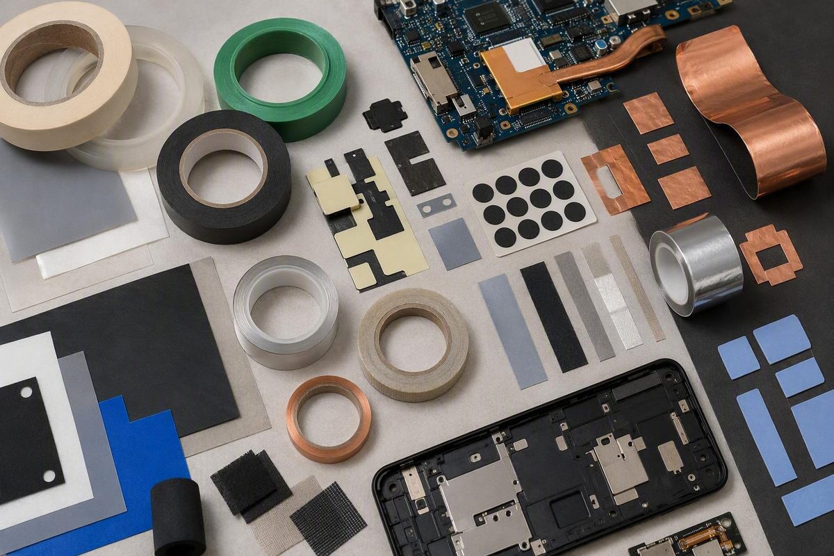
Technical tapes in electronics should be selected as engineered systems, not by a generic label such as “electrical tape,” “foam tape,” or “copper tape.” The backing, adhesive, thickness, geometry, substrates, application process, and operating environment jointly determine whether a tape can bond, mask, insulate, conduct, shield, transfer heat, seal, cushion, or permit later removal.
This is a category-level screening guide, not an engineering approval or substitute for applicable standards. The available technical sources are predominantly manufacturer-, supplier-, or converter-authored, so their application descriptions and qualitative comparisons should not be treated as independent test results. Production approval requires current product-level documentation and testing on representative parts under representative conditions.
What Makes a Tape “Technical” in an Electronics Assembly?
Pressure-sensitive adhesive, or PSA, tape uses an adhesive that bonds when pressure brings it into intimate contact with a surface. It does not require water, solvent, or heat activation. Tapes may be single-sided, double-sided, or supplied as transfer films, as outlined in this technical guide to pressure-sensitive adhesive tape.
Ordinary electrical tape generally emphasizes wire insulation, wrapping, bundling, protection, and identification. A technical electronics tape may instead be designed for a controlled manufacturing process or a specified mechanical, electrical, thermal, shielding, optical, sealing, or release function.
That distinction matters because appearance is a poor guide to performance. Two black tapes of similar thickness could have opposite electrical purposes: one may be dielectric, while another may be conductive.
A practical construction model includes:
- Backing or carrier: Polyimide, polyester, metal foil, conductive fabric, glass cloth, foam, PVC, PTFE, or another engineered material.
-
Adhesive: Commonly acrylic, rubber-based, or silicone, with substantial formulation differences inside each family.
-
Geometry: Width, die-cut shape, holes, tabs, segmented liners, and edge clearances can be as important as chemistry.
- Format: Single-sided tape covers or wraps a surface; double-sided tape joins surfaces; transfer tape leaves adhesive without a permanent carrier.
Technical tapes also fall into two broad use classes.
They must survive the process and then release with acceptable force, residue, and substrate impact.
They may attach a display, sensor, battery, lens, PCB, gasket, heat spreader, wire, or enclosure component for the intended service life.
A die-cut part can sometimes perform several functions. A bezel tape might attach a display while helping seal its perimeter and cushion impact. A conductive gasket might close an enclosure seam while helping maintain electrical continuity. An adhesive gap pad might provide attachment and a heat-transfer path. Supplier application catalogs describe these roles across smartphones, displays, notebooks, wearables, accessories, and smart-home products, but those examples do not establish universal suitability for a specific device.
Multifunctionality should reduce part count only after each function has been verified. A thermally conductive construction may not provide the required electrical isolation. Conductive foil applied to one enclosure seam may not resolve a system-level emissions problem.
Start With the Function: Bond, Mask, Insulate, Conduct, Shield, or Transfer Heat
Start with the job the tape must perform, not the material that looks familiar. The following table is a screening tool, not an approval specification.
| Task | Likely construction families | Critical properties | Common failure modes | Validation checks |
|---|---|---|---|---|
| Bond displays, sensors, batteries, lenses, housings, or boards | Thin double-sided film, transfer adhesive, thin foam, structural foam | Adhesion to both substrates, bond-line thickness, peel, shear, creep, impact response, anti-lift behavior, removability | Edge lift, creep, foam split, adhesive transfer, substrate damage | Peel and shear on production surfaces; static-load, drop, aging, and removal tests |
| Mask PCBs during soldering | Polyimide or another qualified heat-resistant process tape | Peak temperature, exposure duration, dimensional stability, residue, removal force | Shrinkage, adhesive flow, residue, tearing, heat damage | Run the complete thermal profile and inspect protected and adjacent areas |
| Mask plating, cleaning, etching, or coating | Polyester, polyimide, or another chemically compatible process tape | Chemical resistance, edge sealing, conformability, cleanliness, removability | Chemical ingress, edge lift, contamination, incomplete removal | Expose representative masked parts and inspect the mask boundary |
| Insulate wires, coils, transformers, capacitors, or motors | Polyester, polyimide, glass cloth, PVC, fluoropolymer | Product-level dielectric and voltage data, temperature rating, flame requirements, abrasion resistance | Puncture, tracking, dielectric failure, unraveling, thermal degradation | Electrical testing after wrapping, processing, and environmental aging |
| Ground, dissipate static, connect points, or repair circuits | Copper foil, aluminum foil, conductive fabric | Installed resistance, adhesive conductivity, current path, flexibility, termination method | Open circuit, unstable resistance, adhesive-layer isolation, cracked foil | Measure continuity through the installed stack and after flexing or aging |
| Control EMI/RFI | Conductive foil or fabric, conductive gasket tape | Performance over relevant frequencies, seam continuity, grounding, corrosion compatibility | Shielding gaps, poor ground termination, oxidation, seam opening | System-level emissions or immunity testing plus seam-resistance checks |
| Attach a heat source to a heat sink or enclosure | Qualified thermal-interface tape or adhesive gap pad | Thermal resistance, bond-line thickness, contact area, pressure, electrical insulation, aging | Hot spots, interface separation, creep, excessive thickness | Thermal testing in the assembled geometry under expected power and environment |
| Seal, gasket, cushion, or damp vibration | Open- or closed-cell foam, elastomeric tape, film tape | Compression, recovery, permeability, adhesion, environmental resistance | Compression set, leakage, edge lift, creep, tearing | Compression, leak, vibration, aging, and dimensional checks |
| Protect surfaces temporarily | Low-adhesion film tape or protective film | Surface compatibility, cleanliness, controlled release, abrasion resistance | Residue, staining, coating pull-off, trapped contamination | Removal tests before and after processing and storage |
| Manage wires and harnesses | PVC, fabric, friction, glass cloth, polyester | Abrasion, flexibility, insulation, wrap tension, chemical and temperature exposure | Flagging, unwind, damage to insulation, adhesive ooze | Wrapped-assembly inspection, flexing, abrasion, aging, and removal evaluation |
For permanent component bonding, thin double-sided tapes conserve space and distribute load over the bonded area. Foam adds compliance and can accommodate modest irregularities. Neither construction is automatically structural; the joint must be assessed under its actual peel, cleavage, shear, impact, vibration, and sustained loads.
Wave soldering, plating, solvent cleaning, etching, and conformal-coating application impose different thermal and chemical demands. Commercial electronics-tape catalogs illustrate the wide range of polyimide, polyester, foil, cloth, and PVC constructions used for these different tasks.
For dielectric insulation, require product-specific voltage, dielectric, temperature, flame, thickness, and compliance information. The reputation of a backing material is not a rating for the complete tape, especially where layers overlap, edges move, or the adhesive encounters heat or chemicals.
For conductive work, define whether the objective is low-current continuity, static-charge dissipation, grounding, point-to-point connection, circuit repair, or EMI/RFI control. These functions can require different resistance levels, geometries, terminations, and qualification methods.
For thermal management, use a product documented as a thermal-interface material. Thermally conductive tape and adhesive gap pads are intended to transfer heat while providing attachment or gap accommodation. Ordinary mounting foam may instead impede heat flow.
Sealing, moisture blocking, cushioning, impact protection, surface protection, vibration damping, and wire management are also legitimate tape functions, but each creates separate requirements. A cushioning foam can creep. A sealing tape can trap contamination. A protective film can pull away a coating during removal.
Insulating, conductive, shielding, and thermal-interface tapes are not interchangeable, even when their color, thickness, or backing looks similar.
Backing and Carrier Materials: What Each Construction Contributes
The backing provides mechanical, dimensional, electrical, thermal, and handling characteristics. The adhesive determines how that backing attaches and whether the interface supports or obstructs the intended function.
| Backing or carrier | Common electronics roles | Useful construction traits | Main cautions |
|---|---|---|---|
| Polyimide | High-temperature process masking; wire, coil, transformer, capacitor, and flexible-circuit insulation | Thin, dimensionally stable, commonly associated with heat-resistant and dielectric applications | Adhesive chemistry and exposure duration may set lower limits than the film; verify residue, voltage, and chemical performance |
| PET/polyester | Moderate-temperature masking, coil wrapping, insulation, surface protection | Thin, mechanically robust, readily converted, available with multiple adhesive systems | Confirm electrical, chemical, temperature, and removal ratings for the product |
| Copper foil | Grounding, point-to-point connection, circuit repair, EMI/RFI seams | Conductive backing; useful where low resistance or solderability matters | Through-adhesive conductivity is not automatic; soldering heat can damage the adhesive |
| Aluminum foil | Shielding, conductive paths, sealing, reflective surfaces, process masking | Conductive, lightweight, conformable in thin gauges | Joining method, oxide behavior, tearing, corrosion compatibility, and through-adhesive resistance require assessment |
| Conductive fabric | Flexible shielding, wearables, complex enclosure shapes | Conformable and more tolerant of movement than rigid foil | Resistance and shielding depend on coating, weave, adhesive, seam design, compression, and frequency |
| Glass cloth | High-temperature insulation, coil banding, crossover wrapping | Woven reinforcement, abrasion resistance, dimensional stability | Verify breakdown voltage, flame behavior, thickness, edge fraying, and thermal rating |
| Foam | Gap filling, mounting, gasketing, cushioning, vibration control | Compliance, stress distribution, accommodation of rough surfaces | Adds thickness; may creep or take compression set; is not inherently thermally conductive |
| PVC | Harnessing, bundling, identification, abrasion protection, general insulation | Flexible, conformable, widely available in different colors and thicknesses | Verify temperature range, flame requirements, adhesive flow, plasticizer interaction, and aging |
| PTFE or another fluoropolymer | Chemical-resistant masking, release surfaces, dielectric insulation | Commonly associated with chemical resistance, low friction, and dielectric properties | Often difficult to bond; adhesive anchorage, seams, creep, and process compatibility remain product-specific |
Polyimide
Polyimide is widely associated with high-temperature masking and electrical insulation. Some commercial guidance cites short-term capability up to 260°C, but that figure cannot be transferred to every polyimide tape. Adhesive chemistry, total construction, dwell time, heating rate, tension, and chemical exposure may impose lower limits, as the underlying vendor article itself does not provide product-level test conditions for the broad claim (commercial overview of tapes in PCB manufacturing).
Treat any peak-temperature figure as a screening clue until the current product datasheet defines whether it is a short-term or continuous limit and under what conditions it applies.
Polyester
PET or polyester film is commonly considered for moderate-temperature masking, coil wrapping, electrical insulation, and temporary surface protection. It can provide a thin, consistent carrier, but its usable temperature range, chemical resistance, residue behavior, and dielectric performance belong to the complete tape—not to polyester film as a universal class.
Metal foils and conductive fabrics
Copper foil is commonly selected where low resistance, formability, or solderability matters. Aluminum foil may suit conductive, shielding, sealing, reflective, or masking functions. Conductive fabric is useful where flexibility and conformability matter more than a continuous metal sheet.
Metal backing conductivity does not prove continuity through the adhesive. A nonconductive adhesive can isolate the backing from the bonded surface. Even when copper foil can be soldered, excessive heat may degrade or displace the adhesive. A conductive-tape supplier guide distinguishes particle-filled conductive adhesives from constructions that conduct mainly through the backing and summarizes the general trade-offs among copper, aluminum, and conductive fabric (conductive-tape buyer’s guide).
Glass cloth, foam, PVC, and friction tape
Glass-cloth tapes are candidates for coil banding, crossover wrapping, and high-temperature insulation because the woven carrier provides reinforcement. Approval still depends on verified voltage, flame, thermal, thickness, and abrasion properties.
Foam supplies compliance. It can fill a gap, improve contact on textured surfaces, cushion a component, distribute stress, or damp vibration. That compliance can also introduce creep, compression set, thickness variation, and thermal resistance. “Foam” describes a structure, not a heat-transfer capability.
PVC and friction tapes appear in harnessing, bundling, abrasion protection, temporary binding, sealing, identification, and general insulation. Production evaluation should consider unwind, flagging, wrap tension, aging, adhesive flow, plasticizer interaction, and applicable electrical or flame requirements.
PTFE and related fluoropolymers
PTFE and related fluoropolymer backings are associated with chemical resistance, low friction, and dielectric performance. Their low wettability can make adhesive anchorage difficult, while creep or dimensional behavior may matter under load.
Manufacturer catalogs demonstrate the breadth of available PET, glass-cloth, polyimide, PTFE, metal, and thermal-interface constructions, with screening filters such as thickness, adhesive type, breakdown voltage, and thermal conductivity. Those filters can identify candidates, but they are not substitutes for the selected product’s datasheet.
Adhesive Chemistry and Surface Compatibility
Backing selection answers only part of the question. The adhesive must wet both substrates, survive the process and environment, and retain the required balance of peel, shear, tack, creep resistance, and release behavior.
Rubber-based, acrylic, and silicone systems
As broad category tendencies:
- Rubber-based adhesives are commonly associated with high initial tack and useful adhesion to some difficult surfaces. Resistance to heat, oxidation, ultraviolet exposure, and chemicals varies by formulation.
- Acrylic adhesives are commonly associated with UV and environmental stability and may continue developing bond after application. Performance on low-surface-energy materials varies widely.
- Silicone adhesives are commonly considered for high-temperature exposure or bonding to silicone surfaces. They are not automatically suitable for every hot, electrically sensitive, or contamination-controlled assembly.
These tendencies are not rankings. A modified acrylic may bond where another acrylic does not, and two silicone systems can differ substantially in residue, shear, and electrical behavior.
Tack is not final bond performance
Pressure-sensitive tape can provide useful handling strength immediately after pressure is applied. That initial hold is not proof of final bond strength or long-term reliability.
Bond performance may develop as the adhesive wets the microscopic contours of the substrate. Some acrylic systems may require substantial conditioning before assessment; one supplier guide notes that certain acrylic adhesives are evaluated after 72 hours (PSA chemistry and bond-development guidance). That period is not universal. Follow the exact product’s stated dwell and conditioning instructions.
Surface energy, roughness, and cleanliness
An adhesive bonds only where it makes intimate contact. Selection should account for:
- Surface energy and wettability
- Texture and roughness
- Coatings, inks, paints, and passivation layers
- Dust, grease, moisture, and process residue
- Mold release, plasticizer, or migrating additives
- Application temperature
- Pressure and pressure uniformity
- Joint curvature and elastic restoring force
Polyethylene, polypropylene, silicone, and PTFE are difficult substrates for many general-purpose adhesives because of their low wettability or low surface energy. Specialized adhesive formulations or validated surface treatment may be required. Potential methods include primer, plasma, corona, or flame treatment, as described in a manufacturer-authored primer on PSA bonding and surface preparation.
Process settings and the allowable delay between treatment and bonding should therefore be controlled and verified.
Dust and grease form barriers between adhesive and substrate. Moisture can obstruct contact or interact with a coating. Cold application reduces adhesive flow and wet-out.
A practical preparation sequence is:
- Verify compatibility among the tape, substrate, coating, cleaner, and any proposed treatment.
- Clean by an approved procedure that removes relevant contamination without damaging the surface or leaving residue.
- Dry completely and protect the surface from recontamination.
- Apply within the product’s stated temperature range.
- Use the specified pressure across the complete bond area without stretching the tape or trapping air.
- Allow the stated bond-development time before qualification testing or full loading.
Do not qualify only the nominal substrate name. Changes in paint, anodizing, molded resin grade, release agent, plasticizer, supplier, cleaner, or surface treatment can alter adhesion and should trigger appropriate verification.
Application Mini-Guides for Common Electronics Jobs
The following checklists are proposed screening and qualification questions. They do not define universal acceptance thresholds.
PCB processing
First identify what the mask must survive: reflow or wave-solder heat, plating chemistry, cleaning solvent, etchant, conformal coating, or a sequence of processes. Record both peak conditions and exposure duration rather than asking only whether the tape is “high temperature.”
Geometry matters as well. A tape that performs on a flat coupon may lift around connector pins, board edges, vias, or sharp steps. Removal must also be evaluated on the real board so that residue, tearing, solder-mask damage, or disturbance of nearby components can be detected.
Do not approve without:
- Product-specific temperature limits and applicable exposure duration
- Compatibility evidence for the actual flux, cleaner, bath, etchant, or coating
- Residue and removal-force results after the complete process
- Confirmation of edge sealing and protected-area geometry
- Inspection for damage to the PCB finish and adjacent components
Display and lens bonding
Display and lens joints combine restricted space with demanding load cases. Define bond-line thickness and the actual bezel, lens, and housing materials, including paints, inks, and anti-fingerprint or other treatments.
Assess sustained shear, push-out, edge lift from curved or stressed parts, and dynamic loading from drop or impact. If the tape contributes to sealing, evaluate the complete perimeter, corners, cutouts, and compression. If the bond lies in the viewing path, specify optical requirements such as clarity, haze, bubbles, color, contamination, and visible edge quality.
Serviceability changes the joint design. A removable display may need a controlled peel path, pull tab, local heat, or planned access point. Both service-life retention and repair behavior require verification.
Do not approve without:
- Thickness and dimensional tolerances
- Adhesion data for both production substrates and coatings
- Relevant static-load, push-out, shear, impact, and aging results
- Optical specifications where the bond is visible
- Sealing evidence if the tape forms an environmental boundary
- A validated removal procedure if serviceability is required
Battery and sensor mounting
Separate basic attachment from any additional functions the joint may need. Define component mass, static and dynamic loads, thermal exposure, allowable movement, electrical isolation, cushioning, alignment, and service-removal requirements.
A tape may hold a small component during routine handling yet creep under sustained heat. For battery assemblies or any application in which detachment could create a hazard, whether additional retention is required is an application-specific hazard-analysis and standards question—not a conclusion that can be drawn from a tape category.
Do not approve without:
- Representative static and dynamic load testing
- Relevant thermal and environmental aging
- Electrical-isolation evidence where required
- Compression, alignment, and cushioning limits
- A service-removal and damage assessment
- A documented hazard-analysis decision on retention
Heat-sink attachment
Specify a documented thermal-interface tape or adhesive gap pad. Do not substitute ordinary mounting foam merely because it adheres to both surfaces.
Thermal conductivity is only one input. Installed performance also depends on thermal resistance, contact area, bond-line thickness, pressure, flatness, voids, surface finish, electrical insulation, aging, and heat cycling. Mechanical loading from component mass, orientation, vibration, and differential expansion must be evaluated separately.
Do not approve without:
- Product-specific thermal data and the associated test method
- Installed bond-line thickness and pressure requirements
- Assembly-level temperature or thermal-resistance results
- Electrical-insulation data where needed
- Relevant thermal-cycling and aging results
- A documented retention assessment based on the application’s hazards and requirements
Enclosure shielding and grounding
Choose among copper foil, aluminum foil, and conductive fabric according to the required electrical path and physical design. Copper may be useful for low-resistance paths or soldered terminations; aluminum has different joining and surface considerations; conductive fabric may conform more readily around irregular or moving features.
Map the path through every interface: backing, adhesive, overlap, seam, ground point, coating, enclosure, and fastener. For shielding, include seams, apertures, corners, compression, ground termination, and the relevant frequency range.
The actual materials, coatings, humidity, contaminants, and service environment require application-specific review.
Do not approve without:
- Surface and through-adhesive resistance information
- Continuity measurements across installed seams and grounds
- Shielding results over the relevant frequency range
- Relevant flex, vibration, humidity, and aging results
- Application-specific corrosion evidence
- Defined termination and installation procedures
Coils, transformers, motors, and harnesses
For insulation and wrapping, check dielectric and breakdown properties, temperature class, flame requirements, abrasion, wrap geometry, winding tension, and chemical exposure. Edges, overlaps, crossover points, and cut ends may control performance more than the broad taped area.
Half-lapping—overlapping successive turns by approximately half the tape width—is described as general category guidance in the GlobalSpec cable and electrical tape selection guide. Critical work should follow the tape manufacturer’s instructions and the assembly’s applicable requirements rather than treating that overlap as universal.
Do not approve without:
- Product-level dielectric, voltage, thermal, and flame information
- Defined overlap, tension, layer count, and termination method
- Abrasion and flex testing on the wrapped assembly
- Relevant chemical and thermal-aging results
- Inspection criteria for wrinkles, gaps, cuts, and edge lift
Conductive, EMI-Shielding, and Thermal Tapes: Avoid the Common Category Errors
The most consequential selection mistakes often begin with an imprecise label.
Insulating and conductive tape do opposite jobs
Insulating tape is intended to resist current flow. Conductive tape is intended to create an electrical path. Neither label establishes a complete design rating. An insulating tape still requires verified dielectric and temperature data, while a conductive tape requires measured resistance through the installed interfaces.
Conductive adhesive may contain metallic particles such as silver, copper, or nickel. A tape with nonconductive adhesive may conduct mainly along the metal or fabric backing, not through the adhesive to the substrate.
Therefore:
- Do not infer through-thickness conductivity from a metal backing.
- Do not assume an adhesive overlap creates a conductive seam.
- Do not assume foil attached to painted metal is grounded.
- Measure continuity through the complete installed stack.
- Repeat measurements after relevant flexing, heat, humidity, vibration, or aging.
EMI/RFI shielding is a system property
Shielding effectiveness is commonly expressed in decibels, but no universal attenuation value applies to “copper tape,” “aluminum tape,” or “conductive fabric.” Performance depends on frequency, material, thickness, adhesive conductivity, seams, openings, grounding, geometry, and enclosure design.
A highly conductive foil can perform poorly if its adhesive isolates it from ground or a seam opens. A flexible conductive fabric may be preferable where it maintains contact around a moving or irregular joint. The choice must follow system measurements rather than an unsupported material ranking.
Copper generally offers useful conductivity and solderability, although soldering heat can damage the adhesive. Aluminum is lightweight and conductive but may require different surface and joining controls. Conductive fabric offers flexibility and conformability, with performance dependent on coating, construction, installation, and compression.
Thermal conductivity is not thermal resistance
That distinction separates three constructions that are often confused:
- Thermally conductive tape: A relatively thin adhesive construction intended to bond while transferring heat.
- Adhesive gap pad: A compliant thermal-interface construction intended to bridge a defined gap while transferring heat and potentially providing attachment.
- Thermally insulating foam: A foam intended to restrict heat flow, cushion, or isolate regions.
Electronics converters identify both thermally conductive films and adhesive gap pads among possible bonding materials, while emphasizing that selection depends on the substrates and design requirements (electronics bonding overview). Verify device temperatures or interface resistance in the actual assembly after relevant aging; neither the word “thermal” nor visible filler establishes acceptable installed performance.
Tape vs. Liquid Adhesive vs. Mechanical Fastening
No joining method wins universally. Compare candidates by joint geometry, substrates, manufacturing process, service environment, rework needs, risk, and total process cost.
| Consideration | Pressure-sensitive tape | Liquid adhesive | Mechanical fastening |
|---|---|---|---|
| Initial handling | Often provides immediate handling strength | May require cure or drying before loading | Usually immediate once installed |
| Joint geometry | Best suited to accessible surfaces with controllable bond lines | Can fill irregular, confined, or complex joints | Requires room for hardware, tooling, and load-bearing features |
| Thickness control | Available in defined film or foam thicknesses | Depends on dispensing, flow, spacers, and cure | Set by component geometry and clamp-up |
| Load distribution | Spreads load across bonded area | Can spread load across bonded area | Often concentrates load near holes or contact points |
| Repositioning | Usually limited after firm contact | May permit positioning before cure | Often possible before final tightening |
| Process needs | Liner removal, placement, pressure, dwell, waste handling | Dispensing, mixing where applicable, cure, fixturing, cleanup | Hardware feeding, alignment, torque or installation control |
| Rework | Possible with a suitably designed removable system, but not assured | Ranges from serviceable to destructive | Often favorable when designed for disassembly |
| Compliance | Thin film offers little; foam can cushion and fill modest gaps | Formulation can fill gaps or cure in complex spaces | Limited unless washers, springs, or gaskets are added |
| Automation | Die-cuts and liners can support automated placement | Automated dispensing is possible but requires fluid control | Automated insertion is possible but requires hardware handling |
| Main risks | Poor wet-out, creep, edge lift, residue, liner or placement errors | Voids, cure variation, mixing errors, contamination, squeeze-out | Added space and mass, loose hardware, local stress, cosmetic effects |
Tape can offer immediate handling strength, no liquid dispensing, precise die-cut placement, thin joints, distributed loading, cushioning, and automation compatibility. Converted parts can include tabs, holes, alignment features, and segmented liners.
Liquid adhesives may be preferable for irregular, confined, or complex joints where preformed tape cannot make complete contact. They can permit positioning before cure and fill a controlled volume, but may require dispensing controls, mixing, cure time, fixturing, ventilation, and cleanup.
Mechanical fasteners may suit designs prioritizing disassembly, high loads, independent retention, or larger safety margins. Their trade-offs can include space, mass, tool access, appearance, hardware control, and localized stress.
Foam tape can accommodate uneven surfaces and vibration, but its thickness affects tolerances. Sustained load and heat may introduce creep, and the foam may impede heat flow unless it is a qualified thermal-interface construction.
Repairability requires dedicated testing. Removable, stretch-release, or thermal-release tapes may support component recovery, but clean release after prolonged heat, load, humidity, or chemical exposure cannot be assumed. Evaluate release force, residue, substrate damage, component deformation, and the practicality of the service process.
A fair process comparison should include:
- Throughput and labor
- Equipment and floor space
- Fixturing and cure inventory
- Liner handling and waste
- Storage and shelf life
- Inspection method
- Placement or dispensing yield
- Rework time and recovery yield
- Automation and maintenance
- Material traceability
The ASPEC framework organizes joining selection around assembly, substrate, process, end use, and cost, illustrating why unit price alone is incomplete (3M industrial bonding selection guide). Its comparisons are manufacturer-authored guidance rather than independent cost or performance findings.
A Qualification Workflow Before Production Approval
A disciplined qualification process converts a category description into evidence for one assembly. The following workflow is an engineering screening framework; it does not prescribe universal test methods or acceptance thresholds.
Step 1: Define the requirements
Document:
- Joint geometry and available bond area
- Both substrates, including coatings, inks, textures, and treatments
- Temporary or permanent use
- Process temperatures, durations, chemicals, pressure, and handling
- Service temperature, humidity, UV, immersion, contamination, and chemicals
- Static, dynamic, peel, shear, shock, vibration, and creep loads
- Electrical insulation, conductivity, grounding, shielding, or ESD functions
- Heat-transfer or thermal-isolation requirements
- Sealing, cushioning, optical, acoustic, or protection functions
- Removal, repair, and end-of-life needs
- Applicable safety, regulatory, standards, and customer obligations
Rank requirements as mandatory, desirable, or irrelevant. This helps prevent an attractive secondary feature from obscuring a missing primary function.
Step 2: Screen current product documentation
Obtain the current technical datasheet and any relevant compliance or test documentation. Check:
- Backing and adhesive chemistry
- Single- or double-sided construction
- Total and individual layer thicknesses
- Liner type
- Peel, shear, tack, creep, or holding-power data
- Test methods, substrates, and conditioning
- Short-term and continuous temperature limits
- Permitted exposure duration
- Dielectric or conductive properties
- Through-adhesive conductivity
- Thermal conductivity or thermal-resistance data
- Flame and environmental ratings
- Chemical resistance
- Shelf life and storage conditions
- Recommended application temperature, pressure, and dwell
- Available dimensions and converted-part tolerances
Do not compare headline values without checking the associated method, substrate, dwell, temperature, peel angle, speed, and units.
Step 3: Prepare representative specimens
Use production substrates rather than idealized laboratory panels wherever possible. Include actual coatings, molding conditions, surface treatments, cleaners, and relevant process variation.
Prepare coupons and complete parts using the intended:
- Cleaning and treatment methods
- Application temperature
- Tape conditioning
- Pressure and application equipment
- Bond-line thickness
- Dwell time
- Die-cut geometry
- Edge clearances
- Liner-removal technique
- Placement sequence
The objective is not to create one perfect specimen but to determine whether the assembly remains acceptable across realistic manufacturing variation.
Step 4: Test the required function
Choose tests from the function rather than habit:
- Bonding: Peel, shear, cleavage, static load, creep, edge lift, drop, shock, and removal
- Masking: Thermal or chemical exposure, edge ingress, residue, tearing, and removal force
- Insulation: Applicable dielectric, breakdown, insulation-resistance, abrasion, and tracking evaluations
- Conductivity: Resistance through the adhesive, along the backing, across seams, and through terminations
- Shielding: System-level performance over the relevant frequency range
- Thermal transfer: Device temperature or interface resistance under representative power, pressure, and orientation
- Sealing: Leak, compression, ingress, and recovery tests appropriate to the enclosure
- Repair: Release force, residue, substrate damage, component recovery, and cycle time
Step 5: Age the assembly
Select exposures relevant to the device rather than applying an arbitrary list. Candidates may include:
- Heat and humidity
- Thermal cycling or thermal shock
- UV exposure
- Cleaning agents and process chemicals
- Immersion or condensation
- Vibration and mechanical shock
- Drop impact
- Sustained static load
- Flexing or repeated movement
- Combined temperature and load
Re-test the required function after aging. Appearance alone does not establish continued bonding, insulation, continuity, shielding, heat transfer, or sealing.
Step 6: Inspect failure modes
Record where and how failure occurs:
- Edge lift or flagging
- Adhesive or backing split
- Interfacial delamination
- Cohesive adhesive failure
- Residue or adhesive transfer
- Coating pull-off or substrate damage
- Adhesive flow or squeeze-out
- Creep and dimensional shift
- Corrosion or discoloration
- Dielectric failure
- Shielding gaps
- Continuity loss
- Thermal-interface degradation
- Compression set or sealing loss
Step 7: Run a production trial
A successful hand-built prototype does not establish manufacturability. A production trial can investigate:
- Placement and registration capability
- Die-cut dimensional consistency
- Liner removal and handling
- Pull-tab accessibility
- Manual or automated feed behavior
- Applied pressure and process repeatability
- Wrinkles, trapped air, and stretched tape
- Inspection feasibility and defect definitions
- Rework procedure
- Material storage and rotation
- Traceability and supplier change controls
These are proposed production questions, not limits established by the cited category sources. Each organization must define controls and acceptance criteria for its own process.
The available evidence does not establish standards, acceptance thresholds, or approval for high-voltage, high-current, battery, medical, automotive, aerospace, or other safety-critical designs. Those applications require the applicable standards, hazard analysis, current product documentation, and qualified engineering review.
Before purchasing or approving a supplier, ask:
- What is the exact product code and current revision?
- Can the supplier provide a current datasheet and relevant test reports?
- Which values are typical, and which are specification limits?
- Under what methods and conditions were they measured?
- Does conductivity pass through the adhesive?
- What are the short-term and continuous temperature limits?
- What pressure, temperature, and dwell are required during application?
- Which substrate treatments are recommended or prohibited?
- What material or process changes trigger customer notification?
- What are the shelf-life, storage, liner, converting, and tolerance requirements?
- Are production-intent samples available for qualification?
- Is application or failure-analysis support available?
Frequently Asked Questions
Is polyimide tape always safe at 260°C?
No. Some commercial guidance associates polyimide tape with short-term capability up to 260°C, but that figure cannot be transferred to every construction. The adhesive, total thickness, exposure duration, heating profile, tension, chemicals, and residue requirement may impose lower limits (commercial overview of polyimide tape in electronics manufacturing).
Check the exact product datasheet, including whether the stated limit is continuous or short term, and run the complete process profile on representative parts.
Does copper or aluminum foil tape conduct through its adhesive?
Not necessarily. Copper and aluminum backings are conductive, but the adhesive may be conductive or nonconductive. A particle-filled conductive adhesive may provide a through-thickness path; a nonconductive adhesive may isolate the foil from the bonded substrate.
Confirm the product specification, then measure resistance through the actual bond stack, overlaps, seams, and grounding points. Repeat the measurements after relevant environmental and mechanical aging.
Can double-sided foam tape be used to mount a heat sink?
Only when the specific product is documented and qualified as a suitable thermal-interface construction. Ordinary mounting foam should not be assumed to transfer useful heat; its thickness and cellular structure may instead add thermal resistance.
Evaluate installed thermal resistance, bond-line thickness, contact area, pressure, electrical insulation, thermal cycling, aging, and mechanical loads. Any need for independent retention must be decided through the application’s hazard analysis and applicable requirements.
How long does pressure-sensitive electronics tape take to reach full strength?
There is no universal time. PSA tape can provide immediate handling strength, but wet-out and bond development may continue after application. The required dwell depends on adhesive formulation, substrate, temperature, application pressure, and test conditions.
Follow the exact product datasheet and do not fully load or qualify the bond before its specified conditioning period. If no period is stated, obtain supplier clarification and establish an appropriate interval through controlled testing.
Can removable electronics tape support repair or recycling?
It can support disassembly and component recovery when the tape and joint are designed for controlled release. Possible approaches include peel tabs, stretch release, thermal release, or an accessible removal path.
That potential is not proof of clean release after service aging. Test service-life retention, disassembly force, residue, substrate or component damage, release temperature where applicable, and removal feasibility at production tolerances. Do not make recyclability claims without traceable evidence for the complete product and recovery process.
Final Selection Rule
Define the tape’s required function first. Then match the backing, adhesive, thickness, and geometry to the exact substrates, manufacturing process, service environment, and removal needs. Distinguish immediate tack from durable performance, and validate the installed assembly rather than relying on a category name, familiar appearance, or supplier superlative.
Use this guide to screen candidates. Require current product-level documentation, applicable standards, representative testing, and qualified engineering review before production approval.